Friday 31 October 2014

Rail Detect Voltage LED Circuit

At this time’s a clean low supply rail detection circuit to outlay peanuts and takes a short time ago 20 minutes before so to make it to. Its power consumption is quite low, so it may perhaps effortlessly be alive built into battery-powered policy. as a replacement for of using an op amp, the circuit is built around three low-cost transistors (Q1-Q3). Diodes D1-D3 form a 1.8V voltage reference (Vref) in favor of the emitter of Q1. If the voltage across the voltage screen formed by R1 and VR1 is fewer than this, Q1 turns on and provisions Q2 with center bias current.

Rail

This turns on Q3 into proportion to this bias current which at that time drives LED1. The brightness of the LED gives an indication of the severity of the low voltage condition. The brighter the LED, the minor the supply voltage. Trimpot VR1 is adjusted so with the aim of LED1 emphatically comes on by the side of the desired low-voltage thrust. The current consumption is typically fewer than 2mA as LED1 is sour. as a final point, the help exposed in lieu of RLED is right and proper for 6-12V process. For other voltages, RLED can take place calculated using the formula RLED = (Vcc - 1.8)/0.01 (this equates to a current of approaching 10mA).

Circuit


Mains Supply Failure Alarm

Whenever AC mains supply fails, this circuit alerts you by sounding an alarm. It also provides a backup light to help you find your way to the torch or the generator key in the dark. The circuit is powered directly by a 9V PP3/6F22 compact battery. Pressing of switch S1 provides the 9V power supply to the circuit. A red LED (LED2), in conjunction with zener diode ZD1 (6V), is used to indicate the battery power level.

Resistor R9 limits the operating current (and hence the brightness) of LED2. When the battery voltage is 9V, LED2 glows with full intensity. As the battery voltage goes below 8V, the intensity of LED2 decreases and it glows very dimly. LED2 goes off when the battery voltage goes below 7.5V. Initially, in standby state, both the LEDs are off and the buzzer does not sound. The 230V AC mains is directly fed to mains-voltage detection optocoupler IC MCT2E (IC1) via resistors R1, R2 and R3, bridge rectifier BR1 and capacitor C1.

Illumination of the LED inside optocoupler IC1 activates its internal phototransistor and clock input pin 12 of IC2 (connected to 9V via N/C contact of relay RL1) is pulled low. Note that only one monostable of dual-monostable multivibrator IC CD4538 (IC2) is used here. When mains goes off, IC2 is triggered after a short duration determined by components C1, R4 and C3. Output pin 10 of IC2 goes high to forward bias relay driver transistor T1 via resistor R7.

Mains

Mains Supply Failure Alarm Circuit Diagram

Relay RL1 energises to activate the piezo buzzer via its N/O contact for the time-out period of the monostable multivibrator (approximately 17 minutes). At the same time, the N/C contact removes the positive supply to resistor R4. The time-out period of the monostable multivibrator is determined by R5 and C2. Simultaneously, output pin 9 of IC2 goes low and pnp transistor T2 gets forward biased to light up the white LED (LED1).

Light provided by this back-up LED is sufficient to search the torch or generator key. During the mono time-out period, the circuit can be switched off by opening switch S1. The ‘on’ period of the monostable multivibrator may be changed by changing the value of resistor R5 or capacitor C2. If mains doesn’t resume when the ‘on’ period of the monostable lapses, the timer is retriggered after a short delay determined by resistor R4 and C3.


Source: EFY Mag

Solid State Hybrid

As opposed to discrete designs, the IA502 uses an IC to drive the power stages. The entire power amplifier circuitry for 2-channels are squeezed into a tiny TDA7250 10-pin IC. All thats required are four power darlingtons and some passive components to complete a high performance stereo amplifier. No biasing is required as the IC auto biases the output transistors. The IA502 lends itself well to multi-channel amplification. A 6~8 channel power amplifier can easily be constructed even by beginners.

The TDA7250cfp This 2-channel hybrid IC is normally configured with TIP142/147 power darlingtons for its output. For those who prefer to use power transistors instead, the TDA7250 can easily be converted. All that is required are a few transistors, 4 additional resistors and some rewiring. This conversion centers mainly on changing the output section to a Sziklai. Sziklai Output In our IA502 on the right, drivers Q1,Q2 are 2SC2238 and 2SA968, and outputs Q5,Q6 are 2SA1216 and 2SC2922 respectively. No instability problems were encountered from this conversion. After a period of run-in, the amplifier remained thermally stable. Is this version worth the extra cost and effort? If one is only interested in something basic, the TIP version would be sufficient. But if one is after sonic performance, I would recommend this version.


Thursday 30 October 2014

Graphic Equalizer Schematic 10 band Mono

Graphic

This really is ten band graphic equalizer for 1 channel (mono) audio program. You will need build 2 similiar circuits for 2 channel (stereo) audio method. This equalizer construct depending on TL074 low sound JFET op-amp that will give you top quality audio output.

Graphic Equalizer Schematic 10 band Mono Part List:

....20= 10KohmsC4= 10nF polyesterC18= 68pF polysterine
R21....40= 1MohmsC5= 47nF polyesterC19= 360pF polysterine
R41= 10KohmsC6= 4.7nF polyesterC20= 36pF polysterine
R42= 1KohmsC7= 22nF polyesterC21= 4.7uF polyester
R43.....52= 2.2KohmsC8= 2.2nF polyesterC22-23= 33pF polysterine
R53.....62= 47KohmsC9= 12nF polyesterC24= 10uF 25V
R63-64-66-67= 47KohmsC10= 1.2nF polyesterC25-26= 47uF 25V
R65= 10KohmsC11= 5.6nF polyesterC27...32= 47nF polyester
R68-69= 47 ohms 1/2WC12= 560pF polysterineIC1...3= TL074
RV1....10= 100Kohms lin FADERC13= 2.7nF polyesterS1= 2X4 SW for stereo
RV11= 10Kohms log.C14= 270pF polysterine
C1= 180nF polyesterC15= 1.5nF polyester
C2= 18nF polyesterC16= 150pF polysterine
C3= 100nF polyesterC17= 680pF polysterine

Nmos Power Amplifier Series Part 2

Power Amplifier with quasi complementary model is the final power amplifier with the transistors of the same type (N all) or (P all), not using transistor pairs. Connecting post part 1, in section 2 is still to review mosfet power amplifier.

Nmos350 / Nmos500
Two output stage configurations capable of delivering up to 350 watts or up to 500 watts into a 4 ohm load.

 Schema Diagram

 Layout Nmos350
Layout Nmos500
Power Supply
Final Set up And Adjustment
No attempt should be made to set up or test a power amplifier module that is not correctly mounted
on a heatsink. Make sure the main power supply is fused and the work area is clear. First check all
your work and make sure the output devices are insulated from heatsink. The set up is done without
an input or a load connected to the power amplifier.
1. Check the power supply is operating correctly and verify the rail voltages. Switch the power
supply off and check with a multimeter that the rail capacitors have discharged.
2. Correctly connect the ground, positive and negative leads to the power amp module.
3. Remove the PCB fuses and replace with 100 ohm 5 watt resistors. Connect a multimeter
that is set to the 20 volt scale across the positive rail 100 ohm resistor.
4. Check that the power supply connections are correct one last time and switch on. If the
multimeter reading goes off-scale, turn off immediately and find the problem. Check also the
100 ohm 5 watt resistors; they may have gone open cct.
5. If everything seems ok adjust VR2 to set the output stage bias current, by measuring the
voltage across the positive rail resistor. Adjust for a reading of 3 volts per output FET pair. I.e.
For a 6 FET board set for a voltage of 9 volts. This equates to a bias current of 30mA per
FET pair or 90 mA total. For a 10 FET board set for a voltage of 15 volts.
6. If everything seems ok, check the output offset voltage and adjust VR1 to achieve an offset of
less than 10 mV.
7. All being well switch off, back off the bias control trimmer (VR2) and replace the 100 ohm
resistors with 10 ohm 1 watt resistors. Switch on again and re-adjust VR2 to get 0.3 volts per
per FET pair across the positive rail 10 ohm resistor.
8. Switch off, remove the resistors and put the fuses back in. Switch on, re-check the offset
voltage and adjust with VR1 if necessary.
The amp module is ready, connect the input and output and enjoy.

Fluorescent Tube Basics

While they have been with us for many years, fluorescent lamps remain somewhat mysterious to most people. This isnt really surprising, since their operation isnt simple. The tube itself contains a mixture of gases, but the active ingredient is mercury. When operated as an arc, mercury vapour emits a vast amount of short-wave ultraviolet light. This is invisible, but phosphors on the inside of the tube itself fluoresce when struck by UV, and are designed to emit visible light. Most of the remaining UV light is absorbed by the glass, which is opaque to ultraviolet (this is why you cant get a suntan from behind a glass window). Refer to Figure 1 to follow the explanation. This also shows a representation of the fitting that was used for the illumination tests. For all tests, only the centre tube was installed, with the others removed to ensure that each lamp was operating under near identical conditions.

Fluorescent
Figure 1 - Wiring Diagram For a Conventional "Troffer" (Fluorescent Light Fitting)

In order to start the arc inside the tube, a starter is used. This is a small neon lamp, with a bimetallic strip contact mechanism built in. When power is first applied, the neon conducts a small current - enough to heat the bimetallic strip, and this causes the switch to close. Once closed, current flows through the filaments at each end of the tube via the ballast, bringing them to working temperature. The ballast limits the current to a safe value. The filaments themselves are fairly rugged, and are typically around 2 Ohms resistance each.

While the switch in the starter is closed, there is no current flow through the neon gas in the starter. The bimetal strip cools and the contacts open. When current drawn through an inductor is suddenly interrupted, a high voltage is generated as the magnetic field collapses. This high voltage will (hopefully) strike the arc in the tube. As most people will have noticed, fluoros usually flicker a few times when turned on. This is usually because the initial strike is insufficient to maintain the arc because the gas temperature is too low. After a few strikes, the temperature is high enough that the arc maintains itself. Maximum light output is usually not achieved for around 5 minutes, but the difference is not very noticeable with tubes in reasonably good condition.

Once the arc is struck (and maintained), the ballast has a new task. An arc has negative resistance, so as the voltage across the tube falls, the current increases. The ballast limits the current to a safe value, as determined by the tubes ratings. With a continuous arc, the voltage across the tube is too low to allow the neon gas in the starter to conduct, so the starter is effectively bypassed. Old tubes will often be unable to maintain an arc, and this is why they flash and flicker, with the starter constantly opening and closing because the arc is not self-sustaining. Since AC is applied to the tube, the arc actually stops and re-strikes on each half cycle, causing the light to flicker at 100 (or 120) Hz. This is normally not visible, but a tube at the end of its life may only conduct fully in one direction. This causes a 50/60Hz flicker that is often visible and annoying to some people.

Because the ballast is an inductor, it should dissipate no power, but this can never be the case in reality. Inductors are wound with copper wire, which has resistance. If nice thick wire were used, this resistance could be minimised, but to do so is very expensive. A compromise is reached where ballast losses are deemed "reasonable", and cause the temperature rise due to power loss to remain within allowable limits. New regulations will soon specify the maximum allowable power loss in ballasts, which will see a return to larger (and more expensive) types than we commonly see today.

Finally, a capacitor is (or should be) installed in parallel with the incoming mains. This is sized to suit the ballast inductance and supply frequency. The capacitive reactance of the PFC (Power Factor Correction) cap should exactly balance out the inductive reactance of the ballast. If this is done properly, the power factor will be 1 - a perfect result. This cannot happen with a fluorescent lamp though, because the current drawn is not linear. The voltage across the tube is a reasonable approximation to a squarewave because of the arc characteristics, and the maximum achievable power factor is normally around 0.9 (90%). Typical fittings manage 0.85 or so (some are better than others).

This means that the current drawn from the mains will be 10% higher than necessary to produce the lamps rated power. This means that for a 36W fluorescent lamp, the minimum attainable current will be around 190mA at 230V because of ballast losses. The ideal current (if power factor correction were perfect) would be 174mA, allowing for a total typical load of 40W.

Fluorescent
Figure 1A - Wiring Diagram For a "Lead-Lag" Fluorescent Fitting

For many commercial and industrial installations, the lead-lag circuit shown above is common. By including the power factor correction cap in series with one of the ballasts, the power factor is brought to around 0.85 as with the approach shown above, but the capacitor is smaller and thus cheaper than would be the case if the ballasts were in parallel.

Note that where 120V (60Hz) mains voltages are used, you may find that ballast is actually an auto-transformer. This is used because the voltage is not quite high enough to ensure reliable operation, and the auto-transformer configuration boosts the voltage. Figures 1 and 1A are for fittings operating from 220-230V, which need no voltage boost for normal operation. Predictably, the circuits for auto-transformer ballasts are different from those shown here, but similar techniques are used.

Wednesday 29 October 2014

Interfacing Keypad and LCD Embedded Microprocessor

This is circuit for interfacing I/O keypad and LCD that can study in laboratory for student to experience interfacing basic I/O devices to the HCS12 microcontroller mounted on the CML12S-DP256 development board. The keypad that using in this circuit is a standard 4 X 4 matrix keypad with 4 rows and 4 columns. This is the figure of the interfacing of keypad.


The DCM-20434 LCD display is interfaced to the MCU’s SPI-0 serial port through a serial to parallel converter as shown in Figure 3. Figure 3 shows the interface connections between the SPI-0 serial port, the 74HC595 (serial to parallel converter) device, and the LCD-PORT. The DCM-20434 LCD should be configured in four bit mode as the schematic shows DB3 through DB0 connected to ground. This is the interface figure.


To interface the LCD display to the HCS12 MCU you must understand how the physical layer interface circuit is constructed (shown in Schematics for Development Board), how to configure and use the SPI serial port (SPI Serial Bus Document), and how to configure and use the LCD display (DMC-20434 LCD Specifications ).

Emergency Power Generator Source


Nearby are many period as soon as even more power generator is looked-for, but not free. If an outlet is not inside spread otherwise plugging into the control panel cigarette lighter is simply not an option, youll happen content with the aim of you partake of the Xantrex Powerpack 600HD. This 600-watt device is an all-in the field of-individual constituent so as to is not merely powerful adequate to start your car, but robust enough to provides portable power in support of miniature appliances -- it even comes with a built-in air AM/FM means of communication and digital timepiece.

Runs Multiple Appliances on a long time ago
With three AC outlets and lone DC socket by your fingertips, the 600HD is the completely power solution meant for nation with demanding applications or else the need to run multiple tons all together. custom it to drive slight power tools or else on your outside worksite so you can cause the piece of work ready even exclusive of an outlet nearby. It wish in addition charge cell phones so you can stay connected.

Built-in vogue AM/FM data lines
This thing too has an integrated AM/FM radio and digital alarm control to provides access to harmony, negotiate data lines and news, weather, and imperative in turn in decisive emergency situations.

Rechargeable Battery
The XPower Powerpack 600HD is powered by a sealed, non-spillable 28AH battery to facilitate can be alive conveniently revitalized from every household AC outlet before DC cigarette-lighter outlet so with the purpose of it can be made willing anytime, anywhere.

Inordinate in support of Outings
The Powerpack 600HD isnt a minute ago for era of need. It is just what the doctor ordered for taking on camping trips before outings everywhere approximately trimming power is wanted to run camcorders, film games, televisions, even your espresso contraption.

Safety Mechanisms
The highlight-rich Powerpack 600HD has a built-all the rage 600 watt inverter and a reverse polarity detector to prevent accidentally clamping the cables on top of the mistaken terminals. A barragraph LED indicator monitors the Powerpacks battery charge level, so it wont take advantage of, and an audible alarm signals element overheat and battery under-voltage conditions. An overload and above-warmth protection is built wearing to ensure longer inverter life.Whether its a trade place or else a camp site, the XPower Powerpack 600HD is the ideal portable power solution. 

With three AC outlets and individual DC socket on your fingertips, the Xantrex 600HD is the desirable power solution on behalf of associates with demanding applications otherwise the need to run multiple tons concurrently. make use of it to direct minute power tools before on your outside worksite so you can step the profession through even exclusive of an outlet nearby. It preference in addition charge cell phones so you can stay connected. This item also has an integrated AM/FM broadcasting and digital alarm regulator with the intention of provides access to melody, chat radio and news, weather, and imperative in turn taking part in important emergency situations.

100W Hi End Audio Amplifier SymAsym5

Symasym5_3
Symasym5, is a "cute" power amplifier, designed with quality but still low price in mind. This resulted in a ClassAB BJT amplifier, using only TO92 transistors for input and VAS, with a reasonable part count. The topology used is well known and consist of a single diffamp for input, plus a 2nd diffamp with current mirror for VAS. This is followed by normal darlington EF outputstage using modern high beta devices. The circuit uses large amounts of feedback over the whole audioband and an unconventional feedback compensation scheme.
Right now symasym is designed to be driven directly from a CD/DVD-player, simply place a 22k poslog stereo pot between player and symasym. (as voltage divider)


Update
The at least change is to reduce C14 from 22pF to 10pF, but i recommend to follow Pavels advice.

I recommend C14 with 10pF also for MJLs, this increases safety margin.

Do not forget to read Pavels Review! A very promising evaluation of the qualities to be expected from symasym. Thanks Pavel !

Another update are the resistors R31/32 to be increased from 22ohm to 47ohm.

Symasym5_3 is an update of v5.2, with an improved board layout concerning power gnd, resulting in lower thd for high frequencies, giving more clarity in sound. The Page for symasym5_2 still exists.

If the gain is too high because symasym is driven from preamp, R30 can be increased from 499ohms to 1k, but in this case R16/19 (22 or 33 ohms, not on schematic, REs to Q1/2) are required to keep feedback at same level and


Some Specs
  • THD: ~0.005% (measured) simd: 0.002%
  • Power into 8ohm: 60 watts
  • Power into 4ohm: 100 watts
  • Gain: 32dB (~1:40)  full output at 0.7v input (0.5v rms)
  • Feedback: 57dB
  • GainBandWidth: ~400Mhz
  • Slewrate: ~20v/us (symetrical)
  • Supply voltage: +/- 36v
  • Biasing: 55ma, ~12mv across a single 0.22 ohm
  • Measurings: RMAA Symasym5  The measuring setup itself is far from perfect, but gives a good idea !
  • Frequency response: 3.2hz to 145khz (-1db) using 4.7uf input cap
  • Phaseshift at 10khz: <3°
  • More will follow !

Schematic

Part List
Transistors:
Device Qty Value Notes
Q1,Q2 2 MPSA18 can be substituted by BC550C (pins reversed !)
Q7,Q8 2 BC546B or maybe 2n5551 (pins reversed !)
Q3,Q9 2 2N5551 OnSemi/Fairchild/Philips
Q4,Q5,Q12 3 2N5401 OnSemi/Fairchild/Philips
T1 1 BD139 or bd135, bd135-16
U$5 1 MJE15030 OnSemi
U$6 1 MJE15031 OnSemi
U$3 1 MJL3281A OnSemi
U$4 1 MJL1302A OnSemi
Capacitors:
Device Qty Value Notes
C14 1 10pF (has been 22pF) Mica
C2,C7 2 100pF Mica
C3,C4 2 330pF Mica
C18 1 47nF Wima MKS2
C5, C6, C10, C11, C16, C17, C20 7 100nF Wima MKS2
C1 1 10uF (4.7uF also fits) Wima MKS2
C8,C9 2 100uF Electrolytic 63v (at least 40v)
C19 1 470uF Electrolytic 16v
C12,C13 2 1000uF Electrolytic 63v (at least 40v)
Resistors:
Device Qty Value Notes
R27,R28 2 0R22 5Watts
R1, R3 2 1R2 2Watts metal film
R4 1 4R7 2Watts metal film
R7 1 10 2Watts metal film
R2 1 10 250mW metal film
R8, R9 2 22 250mW metal film
R31, R32 2 47 (have been 22) 250mW metal film
R26 1 33 250mW metal film
R10 1 68 250mW metal film
R15,R17 2 150 250mW metal film
R11 1 220 250mW metal film
R24,R30 2 499 (or 500) 250mW metal film
R5,R6 2 680 250mW metal film
R13,R23 2 2k 250mW metal film
R12,R14,R29 3 22k 250mW metal film
R18,R20 2 47k 250mW metal film
R22 1 1k pot Piher, small (470ohm might be better)
Miscellaneous:
Device Qty Value Notes
F1,F2 2 2.5T Fuse Slow blow
F1,F2 2 --- Fuse holder
L1 1 --- 0.6mm isolated (enamelled) copper wire wounded around R7 forming the output coil.


Recomended Part
  • All resistors are standard metal film 250mW except: R1/3/4/7, these are 2W metal film, and the 0.22ohm beeing 5W.
    Around R7 is wounded a 0.6mm isolated (enamelled) copper wire forming the output coil. (~12 windings)
    For c19 i used 470uf/16v, all other electrolytics 63v. The 10/100/330pF should be mica-caps.
    The 100nf and 47nf is recommended to be Wima MKS2 (or better), also for C1 i suggest Wima MKS2, 4.7uf is enough.
    For Trimpot i use a Piher. The MPSA18 can be substituted by BC550C, for all other parts i do not recommend changes, especially the feedback network (r29/30) should be kept unchanged, feedback compensation is very delicate for this circuit !
  • Be careful when substituting the MPSA18 with BC550C, the pinout is reversed between these 2 transistors !!!
  • The bias is adjusted via the trimpot (R22). Recommended bias is 55ma, resulting in 12mv across a single 0.22ohms or 24mv across both 0.22ohms. Connect a DMM to the upper wires of these resistors and adjust trimpot until DMM reads wanted voltage.


Symasym5 biasing: (for debugging)

Portable Muscular Bio Stimulator

This is a small, portable set, designed for those aiming at look improvement. The Bio-Stimulator provides muscles stimulation and invigoration but, mainly, it could be an aid in removing cellulite. Tape the electrodes to the skin at both ends of the chosen muscle and rotate P1 knob slowly until a light itch sensation is perceived. Each session should last about 30 - 40 minutes. 

Portable Muscular Bio-Stimulator Circuit diagram :

Portable
Portable Muscular Bio-Stimulator Circuit Diagram

C1 generates 150µSec. pulses at about 80Hz frequency. Q1 acts as a buffer and Q2 inverts the polarity of the pulses and drives the Transformer. The amplitude of the output pulses is set by P1 and approximately displayed by the brightness of LED D1. D2 protects Q2 against high voltage peaks generated by T1 inductance during switching.
Parts :
  • P1-----4K7 Linear Potentiometer
  • R1-----180K   1/4W Resistor
  • R2-----1K8  1/4W Resistor (see Notes)
  • R3-----2K2  1/4W Resistor
  • R4-----100R   1/4W Resistor
  • C1-----100nF  63V Polyester Capacitor
  • C2-----100µF  25V Electrolytic Capacitor
  • D1-----LED  Red 5mm.
  • D2-----1N4007  1000V 1A Diode
  • Q1,Q2-----BC327  45V 800mA PNP Transistors
  • IC1-----7555 or TS555CN CMos Timer IC
  • T1-----220V Primary, 12V Secondary 1.2VA Mains transformer (see Notes)
  • SW1-----SPST Switch (Ganged with P1)
  • B1-----3V Battery (two 1.5V AA or AAA cells in series etc.)
Notes :
  • T1 is a small mains transformer 220 to 12V @ 100 or 150mA. It must be reverse connected i.e. the 12V secondary winding across Q2 Collector and negative ground, and the 220V primary winding to output electrodes.
  • Output voltage is about 60V positive and 150V negative but output current is so small that there is no electric-shock danger.
  • In any case P1 should be operated by the "patient", starting with the knob fully counter-clockwise, then rotating it slowly clockwise until the LED starts to illuminate. Stop rotating the knob when a light itch sensation is perceived.
    Best knob position is usually near the center of its range.
  • In some cases a greater pulse duration can be more effective in cellulite treatment. Try changing R2 to 5K6 or 10K maximum: stronger pulses will be easily perceived and the LED will shine more brightly.
  • Electrodes can be obtained by small metal plates connected to the output of the circuit via usual electric wire and can be taped to the skin. In some cases, moistening them with little water has proven useful.
  • SW1 should be ganged to P1 to avoid abrupt voltage peaks on the "patients" body at switch-on, but a stand alone SPST switch will work quite well, provided you remember to set P1 knob fully counter-clockwise at switch-on.
  • Current drawing of this circuit is about 1mA @ 3V DC.
  • Some commercial sets have four, six or eight output electrodes. To obtain this you can retain the part of the circuit comprising IC1, R1, R2, C1, C2, SW1 and B1. Other parts in the diagram (i.e. P1, R3, R4, D1, D2, Q2 & T1) can be doubled, trebled or quadrupled. Added potentiometers and R3 series resistors must be wired in parallel and all connected across Emitter of Q1 and positive supply.
  • Commercial sets have frequently a built-in 30 minutes timer. For this purpose you can use the Timed Beeper the Bedside Lamp Timer or the Jogging Timer circuits available on this Website, adjusting the timing components to suit your needs.
Disclaimer: we cant claim or prove any therapeutic effectiveness for this device.

Tuesday 28 October 2014

Alarm Sound with Control Switch


The heart of this circuit is IC No. 555. When the alert sound was working, even though the switch will continue to be the same, the sound still does not stop immediately.But it will stops automatically, when a set time period,Depending on the resistance of R3, the circuit so I set a time period equal to 1M for 1 minute 6 seconds.
Alarm
Alarm Sound with Control Switch

The output of IC 555 is triggered by a positive voltage on pin 2,when all switches are connected together.When the something switch is cut off pin 2, it will be negative voltage and the trigger IC 555 will stop. The C1, C4 to protects a noise signal from either switch, which may cause the alarm to be up. This circuit can be used with power supply from 5V to 15V depending on relay sure enough.

20 Watt Class A Power Amplifier Circuit

A single-ended Class-A amplifier is essentially one where there is only one active driven output device. The passive "load" may be a resistor, an inductor (or transformer) or - as in this amplifier - a current sink. Of the three basic options, the current sink offers the highest linearity for the lowest cost, so is the ideal choice.

20W

Some esoteric (some might say idiosyncratic) designs use inductors or 1:1 transformers, but these are bulky and very expensive. Unless made to the utmost standards of construction, they will invariably have a negative effect on the sound quality, since the losses are frequency dependent and non-linear.

This amp uses the basic circuitry of the 60W power amp (see Index), but modified for true Class-A operation - it should be pretty nice! This amp has been built by several readers, and the reports I have received have been very positive.

With simulations, everything appears to be as expected, but although I have yet to actually build it and test it out thoroughly, no-one has had any problems so far. Using +/-20 Volt supplies - either conventional, regulated or using a capacitance multiplier, it should actually be capable of about 22 W before clipping, but expect to use a big heatsink - this amp will run hot.

Stereo to surround sound systems


Circuit quad amplifier or stereo to surround sound systems using the ic tda7375 to power of 7 watts per channel amplifier version quad or dual 15-watt version (stereo). reaching up to 35 watts in mono version.

stereo

The TDA7375 is an integrated circuit quad amplifier class AB audio amplifier capable of working in double bridge or quad amplifiers simple integrated circuit protection system for short, requires minimal external components, available in packages multiwatt 15H (TDA7375H) and multiwatt 15V (TDA7375V). While the first design was for automotive applications, you can use it in a variety of low power applications. This integrated circuit is in an ideal situation where one wishes a reasonable power and a relatively low supply voltage for its operation. This circuit drawn below uses the basic configuration of amplifier quad configuration but using a bridge (Bridge), can be about 4 times the maximum power. In this configuration quad amplifier can be used as an amplifier end of surround sound systems when seven watts per channel has a good power using a minimum of components.

stereo

Operation of the circuit of the audio amplifier with tda7375
The capacitor C8 decouples the internal voltage divider. Capacitors C5 and C6 are the filter to the power supply. The capacitors 2200?F / 16V are output capacitors. Vs is the power supply can be a car battery or a source of 14 volts.

As suggested pleo friend Ronaldo, now this circuit is dynamic, with at least three variations of assembly, and Quad mount, bridge or stereo system 2.1 Stereo + Subwoofer bridge. Suffice it to set a jumper on the card and switch between P (bridge) and N (normal).

An ideal application is in conjunction of 2.1 systems subwoofer filter posted by Buddy A. Junior, which is used as channel 1 and 2 channel stereo and 2 and 3 in bridge mode to Subwwofer. In bridge mode the output capacitors should be omitted.
Anyway you will find the best application for the circuit
Circuit diagram of amplifier with tda7375 – now dynamic

It can be 12V/30VA with a transformer, a bridge rectifier and an electrolytic capacitor or 4700?F (highest). The maximum current consumption with loads of 4ohms is 2.1 A. You can use loads of 2 ohms, but remember also to increase the size of the heatsink, because the integrated circuit package multiwatt will heat a little more. The fuse circuit to be 2A to loads 4 ohms. The maximum voltage is to tda 18 volts, then the working voltage of the electrolytic capacitors is 35 volts. Recommend a source of 15 volts / 2 amps.
Suggested printed circuit board side of the copper

When assembling the circuit remember that this quad amplifier channels features two four inverted, then you should connect the speakers with the polarity reversed on these outputs, the polarity of electrolytic capacitors which must be of good quality. Block diagram of TDA7375 for more information see datasheet pdf of the integrated circuit TDA7375.

Monday 27 October 2014

TDA1524 Stereo Tone Control

Here is a stereo preamplifier circuit with built in tone control facility. A very useful circuit using versatile tone control IC TDA 1524 from Phillips.
Rangkaian
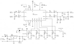
diagram TDA1524 Stereo Tone Control

This circuit is designed as per the data sheet as an effective stereo-tone & volume control for car stereos , TV sets or any sort of stereo amplifier circuit you want.The circuit includes provisions like bass control, treble control , volume control with inbuilt contour or linear mode option (can be switched in betwwen) and balance. All these functions provided can be controlled by DC voltages or by linear potentiometers.

Note:
  • R1 ,R2 ,R3 andR4 can be used for controlling volume, balance, treble and bass respectively.
  • If SPDT switch S1 is in position 1 ,the circuit works in contour mode and in position 2 the circuit works in linear mode.
  • If you are using a 15-20V supply, you can use that as your pre-amp supply as well. Make sure you test the voltage first in all cases

TDA1524 Tone Control Component:
R1,R2 : 220R Resistor
R3,R4 : 4K7 Resistor
R5 : 2K2 Resistor
R6 : 1K Resistor

C1,C2,C7,C8,C17 : 10 uF ecap
C3,C4 : 47 nF
C5,C6 : 15 nF
C9 : 220 nF poly
C10 : 100 uF 25V
C11,C12,C13,C14,C16 : 100 nF
C15 : 1000 uF 35V
C18,C19 : 10 nF

IC1 : TDA 1524A
IC2 : LM 7812
P1 : 50k linear switch pot
P2,P3,P4 : 50k linear pot
X1,X2,X3,X4 : RCA jack
D1 : Diode 1N4004
L1 : Red LED

Stereo High Power Audio Amplifier


This is a stereo amplifier circuit which has a high output power and excellent sound quality. Amplifier circuit has a very high gain output stage resulting in the deterioration of signal noise distance. This amplifier circuit having an output power of more than 400 Watt x 2 (Stereo) with the speaker impedance 4 Ohm - 8 Ohm. Power supply voltage circuit to supply this high power amplifier with maximum - + 75 Volt DC. Heres the scheme of High Power Amplifier :

High Power Amplifier Circuit Diagram


IC Amplifier with HA13118 Diagram

IC amplifier 18 watt circuit is an IC digit HA13118 Hitachi powerfully. with the intention of the IC yearn for take place integrated amplifiers, categorize AB. And this cycle is to assistance a association circuit. to the same degree a answer, growth toll up to 55 dB. And pressure from 8-18 volt the current 1-2 amps, with not as much of than 0.2% distortion by 1W. And response. frequencies from 30 Hz-30 kHz.

IC Amplifier with HA13118 Circuit Diagram
As entering the power supply circuit, and paid into the audio input. The audio is through VR1 adjusts the level of the audio sign. And pass the C1 coupling signal. The C2 eliminate the interference. From the audio signal to come to pass sent through to the input pin on pin 3 of IC1. so as to this circuit to circuit modish the form of conduit circuits otherwise expansion of the not here navigation. And restore channels laid back, to follow a elevated watt power. The observations from the pin 15 which is the output of absent channel speakers are connected to individual fringe. And the other side of the speakers are connected to the output of pin 8, which is the output of the right. The C7 and C8 acting reaction hint to the circuit’s frequency response is better. The C9, C10, R1 and R2 willpower wait on unconcerned the campaign. And C11, C12 serve to filter the light as it should be to prevent several din shock.

USB cable signals

USB cable consists of 4 wires plus a conductor wire wrapping, such as the protectors are usually found in the audio cable. Cable number 1 is used to channel resources to the voltage of 5 volts, if necessary USB devices may draw power from this line and should not exceed 100 mA. Computer equipped with USB capability, is required to provide power at 100 mA for this purpose. USB devices that require more power than the aforementioned provisions, must provide their own resources for the purposes work equipment.


The USB cable signals

Number 4 is the ground cable as a back channel source voltage of 5 volts. Cable number 2 and number 3 is used for signal transmission. No. 2 cable and cable called D-3 numbers called D, the voltage on the two channels is changed between 0 Volt and 3.3 Volt. Digital signal is sent through the two channels are said to be difference signal, which means that the signal digital 0 or 1 is not declared to the magnitude of the voltage on the channel to the ground, as well as digital signals used in the IC TTL (transistor Transitor Logic) or the RS232 channel.

Digital signal is expressed by the voltage difference between the two cables. If the voltage on the D channel is higher than the voltage at D-channel, then the information transmitted digital signal is 1 , otherwise the digital signal 0 is expressed by the voltage at D

At low speed USB devices, the D-channel to 3.3 Volt dipasangan custody, or in the absence of information transmission, the channel is in state 0 . For full speed USB device, such resistance is connected to the D channel, so that in the absence of data transmission channels are in state 1 .

Sunday 26 October 2014

KA2107 Tone control electronic circuit project

A very simple tone control electronic circuit project can be designed using the KA2107 integrated circuit manufactured by Samsung Electronics . This tone control electronic circuit project is very simple requiring few external electronic parts . As you can see in circuit diagram the KA2107 tone control circuit project is designed for stereo application and it has some additional functions like volume control and balance control between channels . Adjusting the 10k potentiometers (bass and tremble) you will modify the high and low output signal frequency .

This electronic circuit project must be powered from a simple 12 volt Dc power supply circuit , but it works fine also with a 8 volt or 14 volt DC power circuit .

simple

Saturday 25 October 2014

I2C Bus Electrical Isolation Diagram Circuit

When the SDA (Serial DAta) lines on both the left and right lines are 1, the circuit is quiescent and optoisolators IC1 and IC2 are not actuated. When the SDA line at the left becomes 0, current flows through the LED in IC1 via R2. The SDA line at the right is then pulled low via D2 and IC1. Optoisolator IC2 does not transfer this 0 to the left, because the polarity of the LED in IC2 is the wrong way around for this level. This arrangement prevents the circuit holding itself in the 0 state for ever. As is seen, the circuit is symmetrical. So, when the SDA line at the right is 0, this is transferred to the left. The lower part of the diagram, intended for the SCL (Serial CLock) line, is identical to the upper part.

Electrical
Electrical Isolation For I2C Bus Circuit Diagram

Resistors R1, R4, R5, and R8, are the usual 3.3 kΩ pull-up resistors that are obligatory in each I2C line. If these resistors are already present elsewhere in the system, they may be omitted here. The current drawn by the circuit is slightly larger than usual since the pull-up resistors are shunted by the LEDs in the optoisolators and their series resistors. Nevertheless, it remains within the norms laid down in the I2C specification

Friday 24 October 2014

Condenser Pre Amplifier LM 1458

This is a simple preamplifier circuit for electret condenser microphone.
using a LM1458 dual op amp IC. The circuit takes the audio signal rom the condenser microphone and amplifier it, so you can use the microphone as the input to some device which wouldn’t normally accept microphone level signals .

Condenser


Schematic Circuit of Microphone Electret

Condenser Pre Amplifier

The circuit requires a 6-9 volt supply. Output of the microphone amplifier can be made variable by connecting a 10kΩ potentiometer . Circuit’s gain can be increased by men perbesar the value of 47K, depending on the input sensitivity of the main amplifier system. The microphone should be housed in a small round enclosure.


List componet of condenser pre-amp mic circuit

Q1,Q2    : LM1458 Op-Amp
R1,R2,R3 : 4.7k ohm resistor
R4, R5   : 10k ohm resistor
R6,R7    : 47k ohm resistor
C1,      : 0.22uF ceramic capacitor
C2       : 1uF ceramic capacitor


Absolute maximum ratings of LM 1458 IC
Supply Voltage               :  ±18V
Power Dissipation            : 400 mW
Differential Input Voltage   : ±30V
Input Voltage                : ±15V
Output Short-Circuit Duration: Continuous

Operating Temperature Range  : 0°C to +70°C
Storage Temperature Range    : −65°C to +150°C
Lead Temperature             :(Soldering, 10 sec.) 260°C

1 3 12 2 VDC Variable Power Supply

Power supply circuit to generate output below were variations between 1.3V DC to 12.2V DC with 1A current.
1.3
In addition, the power supply circuit is also equipped with over-current protection or shield against belebih flow. Power supply circuit is very simple, but the quality is quite good, made ​​her basiccally regulator IC LM723 is a fairly legendary.

Thursday 23 October 2014

10Mhz to 1 MHz Frequency Converter

10Mhz to 1 MHz Frequency Converter Circuit

10Mhz

Part ListIC1 7404 = 1
IC2 7490A = 1
R 1 K = 2
R 3.3 K = 1
C Trim Polymer 39 pF = 1
C Electrophoresis 4.7 uF 16V = 1
C Milar 47 nF 16 V = 1
C Milar 10 nF 16 V = 1
C Ceramic 68 pF 50 V = 1 

Technology Spending Limits and the Auto Sound System

We live in a world that is constantly changing and evolving. We see it every time we buy a new car, a new television, or a new computer. We see it every other month when the iPod is putting out a new an improved model that offers more features, more disk space, and more everything, in a smaller package (well not since they added video but until then, the gadgets were getting smaller while the features were growing exponentially). The truth of the matter is that technology seems to be advancing at a rate that is nearly impossible to keep up with. That being said, you can quite literally drive yourself insane by trying to keep up with the pace of modern technology.

What you need to do in order to maintain proper sanity is decide on a level of technology that you are comfortable and confident with and go with it until it is time (by either necessity or desire) to upgrade. You do not have to be the first to purchase the latest and greatest in software and gadgetry (this has become my mantra: I do not have to be the first to own the great big bad new toy, I will survive gadget deprivation-it isnt working yet but Im ever the optimist). The point is that you do not need to be the first to try every new thing and you will not only wear yourself out by trying but also you bank account, credit cards, and second mortgage. Technology is expensive, especially the newest and latest. If there was any doubt stroll on over to Ebay and see how much Play Station 3s are selling for at the moment-madness and lunacy do not even begin to subscribe the amount of money people are offering to pay for these devices.

Technology is a wonderful thing. It makes life easier for some and a lot more entertaining for others. The same holds true with auto sound systems. The technology exists to make them much more beneficial to car and driver than they have been in the past while offering many more features than ever before. Today you arent even limited to AM and FM. You now have the option of CDs, audio books, MP3s, XML, and digital FM radio, which offers a few bonus features over traditional radio. It really doesnt matter if you have the absolute latest. Most of us can enjoy a great deal of the wonderful technology that is available if we are willing to wait long enough for the prices to go down. I recall, and it wasnt all that long ago, when DVD players sold for no less than $100. You can get them now (about 5 years later) on a regular basis for less than $30. This is only one example of many. PS2s were around $400 when they first hit the market and now can be bought at the whopping price of $120. All around us technology evolves and grows and then prices fall.

The point is spend your money where you want to spend it rather than where you think it should be spent. If you want an auto sound system then get the best one that you feel meets your budget requirements. You do not have to have the top system in the technology food chain in order to have a great sound system that will provide you with years worth of enjoyment. You are the only one that is responsible for the decisions you make. It is up to you to decide where you want the bulk of your money invested when it comes to technological gadgets and goodies. Believe me, Im a gadget geek. I love playing with new toys and gizmos and seeing how they work-really, for me its a thrill. At the same time I realize I cant always be the first to get the new toys I so desperately want to try out so I limit myself and decide which ones are the most important. You must do this for yourself when it comes to auto sound systems.

3000W Stereo Power Amplifier Circuit

Circuit Power Amplifier has a power output of up to 1500W RMS power amplifier circuit is often used to power sound systems keperlun for outdor. In the final image can be seen a series of power amplifiers using 10 sets of power transistors for the ending.

This power amplifier circuit using a transistor amplifier from the front, signal splitter, driver and power amplifier. Current consumption required is quite large power amplifier that is 15-20 A 1500W power amplifier circuits for this. Supply voltage needed by the power of this amplifier is the optimal working order symmetrical 130VDC (130VDC-130VDC ground). 1500W amplifier circuit below is a picture series of mono, stereo if you want to make it necessary to make two copies of the circuit. For more details can be viewed directly image the following 1500W power amplifier circuit.

The series of High Power Amplifier 1500W With Transistor
Click Image to view larger


In the above series of power amplifer 1500W is equipped to control a DC Offset function to set the power amplifier is turned on at the moment and with no input signal then the output should be 0VDC. Then also equipped with a flow regulator to the power amplifier bias. Final part of this power amplifier requires adequate cooling to absorb the heat generated. Power amplifier is not equipped with a speaker protector, therefore it is necessary diapsang protector on the speaker output so that when the power amplifier is not the case turned on the beat to the speaker that can damage the speaker.